Slicing for Embedded Electronics Housings in Cura
How to Slice for Embedded Electronics Housings with Wire Channels and Mounting Bosses
Estimated reading time: 5 minutes
- Understand the design considerations for effective electronics integration.
- Optimize Cura settings to ensure structural integrity and usability.
- Employ post-processing techniques for a perfect fit.
- Troubleshoot common printing issues for better quality outcomes.
Table of Contents
- Understanding the Need for Customized Electronics Housings
- Designing for Slicing
- Key Cura Slicer Settings for Electronics Housings
- Incorporating Post-Processing for Fine-Tuning
- Troubleshooting Common Issues
- Conclusion: Elevate Your 3D Printed Electronics Housing
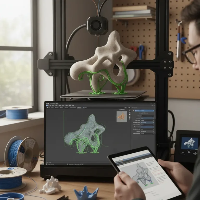
Understanding the Need for Customized Electronics Housings
With the rise of Internet of Things (IoT) devices, wearables, and other context-specific electronics, the demand for tailored enclosures is burgeoning. These specialized housings must not only fit electronic components snugly but should also allow for efficient heat dissipation, accessibility to ports, and comfort in assembly. Key challenges include:
- Managing Space: Efficiently fitting PCBs, wires, and connectors into a confined space.
- Structural Integrity: Ensuring that the enclosure maintains strength, particularly around mounting points.
- Thermal Considerations: Allowing proper ventilation where necessary to prevent overheating.
By mastering the slicing process in Cura, makers and professionals can create enclosures that address these challenges effectively.
Designing for Slicing
Before diving into slicer settings, let’s briefly discuss design considerations. When creating 3D models for electronic housings, be mindful of the following:
1. Wire Channels
Design dedicated pathways for wires to minimize clutter. The channels should have enough width to accommodate the wires without pinching or affecting overall aesthetics.
2. Mounting Bosses
Integrate mounting bosses compatible with your electronic components, ensuring they provide sufficient anchoring without compromising the overall design. Consider the alignment and depth required for screws or standoffs.
3. Tolerancing and Fit
Utilize tolerancing charts to ensure that parts will fit together properly post-printing. Take into account the shrinkage of filament as it cools, which varies among materials.
You can find useful information on tolerancing in the design section of 3D printing documentation, such as this resource from Ultimaker.
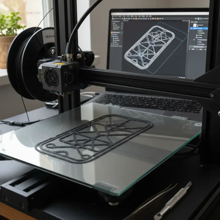
Key Cura Slicer Settings for Electronics Housings
Once your design is finalized in CAD software, it’s time to prepare your model for slicing in Cura. Here are some critical slicer settings to optimize:
Layer Height
Recommendation: Use a layer height of 0.1 mm to 0.2 mm. This provides a good balance between precision and print speed. However, finer layers (0.1 mm) may be necessary for detailed features such as mounting bosses.
Infill Percentage
Recommendation: A 20% to 30% infill typically suffices for most enclosures. If structural integrity is crucial, consider increasing the infill density or switching to a stronger infill pattern like hexagonal or cubic.
Print Speed
Recommendation: Set print speed to 40-60 mm/s to ensure adequate adhesion and reduce defects, especially in detailed sections.
Print Orientation
Recommendation: Position your design based on the internal structure. Always ensure mounting bosses are printed upright to maximize strength. If possible, orient the model to minimize support structures without compromising the integrity of the part. This guide on Cura Speed-Quality Profiles can provide you with helpful insights on how to balance these factors.
Supports and Adhesion
Use of Supports: If wire channels or features require supports, Cura can automatically generate them. Consider the trade-off with post-processing time.
Bed Adhesion: Utilize a brim to enhance bed adhesion and minimize warping. This is particularly useful for larger, flat model bases.
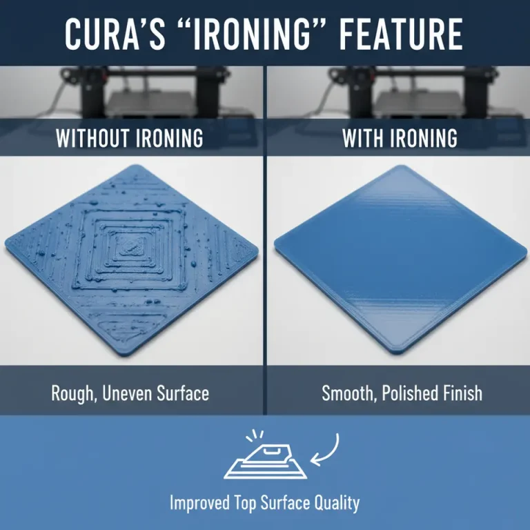
Incorporating Post-Processing for Fine-Tuning
Sometimes, printed parts may still require additional refinement. Post-processing techniques such as sanding or adding rubber grommets around openings can enhance the fit for wires and connectors. You can refer to our detailed guide on installing and using Cura post-processing for more methods to achieve a seamless finish.
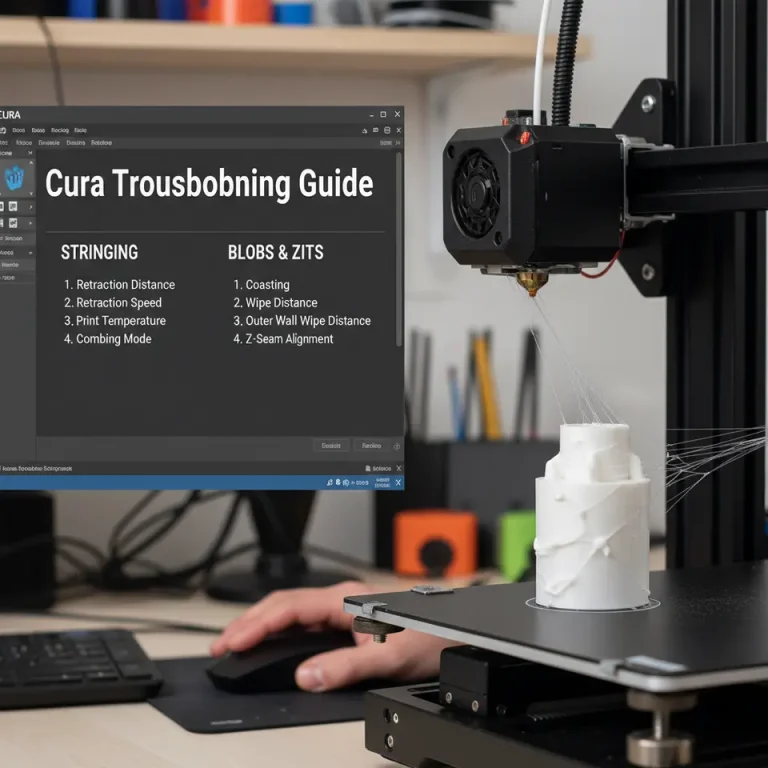
Troubleshooting Common Issues
- Weak Joints: If the mounting bosses are breaking, you may need a higher infill density or consider thicker skirt/brim settings to give added strength.
- Rough Edges: If you’re encountering rough edges around wire channels, experiment with layer height settings or adjust print speed for a smoother surface.
- Warpage: If warping occurs, ensure your bed temperature is adequately set for the material being used, and ensure good octagonal airflow across the build plate.
You can also explore our article on perfecting the first layer in Cura to minimize common adhesion issues.
Conclusion: Elevate Your 3D Printed Electronics Housing
Slicing for embedded electronics housings requires a blend of thorough design planning, appropriate slicer settings, and an understanding of the printing process’s intricacies. By leveraging these techniques in Ultimaker Cura, you can create effective and bespoke enclosures for your electronics projects.
For more tips and in-depth guides on 3D printing and slicing, be sure to check out other articles at CuraSlicers.com, such as our discussions on Cura Stringing Fix Guide and Cura Adaptive Layers Optimization.
Stay ahead in the 3D printing game! Follow us on social media and subscribe to CuraSlicers.com for the latest updates, tutorials, and offers tailored to enhance your printing experience.
By carefully following these guidelines, you can create custom enclosures that effectively accommodate embedded electronics, ensuring functionality meets design and durability needs. Happy printing!